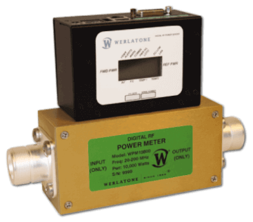
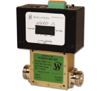
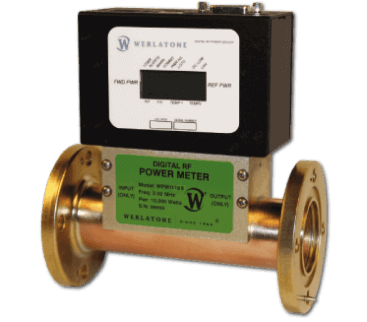
Digital Power Meters
Choose Filters
FILTERS Werlatone Power Meter Windows App - Login Required Werlatone Power Meter Technical Manual - Login Required Werlatone Power Meter LabVIEW Driver - Login Required Werlatone Power Meter MIB - Login Required
| Model | Docs | Cart | Type | Frequency (MHz) | Power (Watts CW) | Connector Type | Interface |
|---|---|---|---|---|---|---|---|
| WPM11356 | Add to Cart | Digital RF Power Meter | 1.5 - 32 | 500 | N-Female | Coaxial | |
| WPM11071 | Add to Cart | Digital RF Power Meter | 1.5 - 32 | 2500 | 7/16-Female | Coaxial | |
| WPM11357 | Add to Cart | Digital RF Power Meter | 1.5 - 32 | 5000 | 7/16-Female | Coaxial | |
| WPM11199 | Add to Cart | Digital RF Power Meter | 1.5 - 32 | 10000 | 1 5/8" EIA | Coaxial | |
| WPM11073 | Add to Cart | Digital RF Power Meter | 1.5 - 32 | 25000 | 1 5/8" EIA | Coaxial | |
| WPM11514 | Add to Cart | Digital RF Power Meter | 1.5 - 32 | 25000 | 3 1/8" EIA | Coaxial | |
| WPM11355 | Add to Cart | Digital RF Power Meter | 1.5 - 32 | 50000 | 3 1/8" EIA | Coaxial | |
| WPM11358 | Add to Cart | Digital RF Power Meter | 1.5 - 100 | 500 | N-Female | Coaxial | |
| WPM11320 | Add to Cart | Digital RF Power Meter | 1.5 - 100 | 1000 | N-Female | Coaxial | |
| WPM11317 | Add to Cart | Digital RF Power Meter | 1.5 - 100 | 2500 | 7/16-Female | Coaxial | |
| WPM11322 | Add to Cart | Digital RF Power Meter | 1.5 - 100 | 10000 | 1 5/8" EIA | Coaxial | |
| WPM11380 | Add to Cart | Digital RF Power Meter | 1.5 - 100 | 10000 | LC-Female | Coaxial | |
| WPM11714 | Add to Cart | Digital RF Power Meter | 2 - 45 | 25000 | 3 1/8" EIA | Coaxial | |
| WPM11323 | Add to Cart | Digital RF Power Meter | 2 - 50 | 200 | N-Female | Coaxial | |
| WPM11324 | Add to Cart | Digital RF Power Meter | 2 - 50 | 1000 | N-Female | Coaxial | |
| WPM11316 | Add to Cart | Digital RF Power Meter | 2 - 50 | 2500 | 7/16-Female | Coaxial | |
| WPM11373 | Add to Cart | Digital RF Power Meter | 2 - 50 | 5000 | LC-Female | Coaxial | |
| WPM11326 | Add to Cart | Digital RF Power Meter | 2 - 50 | 10000 | 1 5/8" EIA | Coaxial | |
| WPM11383 | Add to Cart | Digital RF Power Meter | 2 - 50 | 10000 | 7/16-Female | Coaxial | |
| WPM11386 | Add to Cart | Digital RF Power Meter | 2 - 50 | 25000 | 1 5/8" EIA | Coaxial | |
| WPM11681 | Add to Cart | Digital RF Power Meter | 2 - 128 | 10000 | QC Block | Coaxial | |
| WPM11490 | Add to Cart | Digital RF Power Meter | 10 - 127 | 20000 | LC-Female | Coaxial | |
| WPM11363 | Add to Cart | Digital RF Power Meter | 10 - 200 | 500 | N-Female | Coaxial | |
| WPM11332 | Add to Cart | Digital RF Power Meter | 10 - 200 | 10000 | 1 5/8" EIA | Coaxial | |
| WPM11416 | Add to Cart | Digital RF Power Meter | 10 - 300 | 10000 | LC-Female | Coaxial | |
| WPM11364 | Add to Cart | Digital RF Power Meter | 10 - 500 | 500 | N-Female | Coaxial | |
| WPM11334 | Add to Cart | Digital RF Power Meter | 10 - 500 | 1000 | N-Female | Coaxial | |
| WPM10800 | Add to Cart | Digital RF Power Meter | 20 - 200 | 10000 | LC-Female | Coaxial | |
| WPM11343 | Add to Cart | Digital RF Power Meter | 20 - 520 | 1000 | N-Female | Coaxial | |
| WPM11376 | Add to Cart | Digital RF Power Meter | 20 - 520 | 2500 | 7/16-Female | Coaxial | |
| WPM11335 | Add to Cart | Digital RF Power Meter | 20 - 1000 | 200 | N-Female | Coaxial | |
| WPM11367 | Add to Cart | Digital RF Power Meter | 20 - 1000 | 500 | N-Female | Coaxial | |
| WPM11340 | Add to Cart | Digital RF Power Meter | 20 - 1000 | 1000 | N-Female | Coaxial | |
| WPM11678 | Add to Cart | Digital RF Power Meter | 50 - 500 | 100 | N-Female | Coaxial | |
| WPM11368 | Add to Cart | Digital RF Power Meter | 50 - 500 | 500 | N-Female | Coaxial | |
| WPM11346 | Add to Cart | Digital RF Power Meter | 80 - 1000 | 200 | N-Female | Coaxial | |
| WPM11369 | Add to Cart | Digital RF Power Meter | 80 - 1000 | 500 | N-Female | Coaxial | |
| WPM11235 | Add to Cart | Digital RF Power Meter | 80 - 1000 | 1000 | N-Female | Coaxial | |
| WPM11072 | Add to Cart | Digital RF Power Meter | 80 - 1000 | 2000 | 7/16-Female | Coaxial | |
| WPM11101 | Add to Cart | Digital RF Power Meter | 80 - 1000 | 2500 | 7/16-Female | Coaxial | |
| WPM11350 | Add to Cart | Digital RF Power Meter | 100 - 500 | 200 | N-Female | Coaxial | |
| WPM11351 | Add to Cart | Digital RF Power Meter | 100 - 500 | 1000 | N-Female | Coaxial | |
| WPM11379 | Add to Cart | Digital RF Power Meter | 100 - 500 | 2500 | 7/16-Female | Coaxial | |
| WPM11188 | Add to Cart | Digital RF Power Meter | 380 - 400 | 1000 | N-Female | Coaxial | |
| WPM11510 | Add to Cart | Digital RF Power Meter | 500 - 2500 | 100 | N-Female | Coaxial | |
| WPM11505 | Add to Cart | Digital RF Power Meter | 800 - 2500 | 1500 | 7/16-Female | Coaxial | |
| WPM11667 | Add to Cart | Digital RF Power Meter | 900 - 930 | 5000 | 1 5/8" EIA | Coaxial | |
| WPM11659 | Add to Cart | Digital RF Power Meter | 1000 - 2000 | 2000 | 7/16-Female | Coaxial | |
| WPM11654 | Add to Cart | Digital RF Power Meter | 2400 - 2500 | 5000 | TBR | Waveguide |
Optimal Accuracy
50 dB dynamic Range
No On-Site Calibration
CAPABILITIES
Instantaneous and Simultaneous Local or Remote Monitoring of Forward Power, Reverse Power, and Load VSWR.
(Figure 1,2)
Accuracy
Multi-Octave Solution within ± 5% (± 2% typical) of Customer Lab Standard, Across a Full 50 dB dynamic Range.
Calibration.
No On-Site Calibration Required.
- The Calibration of the each Power Meter is completed internally, allowing the operator to simply enter an RF frequency for optimal accuracy. (Figure 1)
- Traceable to National Institute of Standards and Technology (NIST).
Set Alarm Threshold of Forward Power, Reverse Power, Load VSWR & Temperature.
(Figure 6)
Networkable and SNMP Programmable.
- Multiple units can be networked and simultaneously monitored.
Full VSWR Monitoring/Alarm Capability.
(Figure 1,2)
- Customer can set up a visual alarm via relay.
- Signal can be sent to a Customer’s closed loop.
Full Temperature Monitoring/Alarm Capability.
(Figure 1,2)
- One sensor, Internal Measurement, within Meter.
- Two sensors, External Measurement, to be placed by Customer.
Six General Purpose Inputs/Relays with multiple uses.
(Figure 8)
Powered by AC Power or Passive Power Over Ethernet (PPOE).
Remote Interface
through TCP-IP (with SNMP and Browser Interface via LAN), Passive Power over Ethernet, and RS485 Form Addressable Serial Network.
User ID and Password Protection
provides secure monitoring.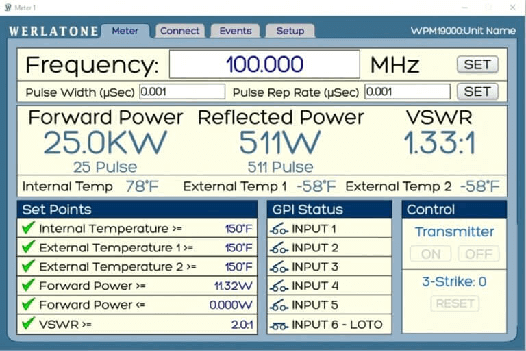
Figure 1
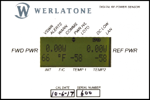
Figure 2
PROGRAMMING AND ADMINISTRATIVE CONTROLS
Programming Capabilities.
- Power Meter is SNMP programmable using Customer’s preferred interface. (A LabView Driver is available for LabView Users).
- Power Meters allow for access to internal network. This will allow for external access to the Meter and for proper email notification. (Figure 3)
- A Static IP address can be used to connect to the Internet directly or through a router.
- Power Meters can send periodic emails by selecting from the Periodic Email pulldown menu. This includes all main screen parameters and a spreadsheet of data for record keeping purposes. (Figure 4)
- Email notification can be set to None, Faults Only, or Warnings and Faults.
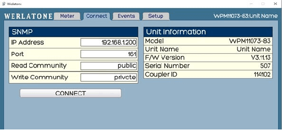
Figure 3
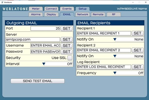
Figure 4
Administrative Controls.
- Customization of a Power Meter name, as displayed remotely. Ability to enter a site name or location. (Figure 5)
- Power may be displayed as kW, W, or dBm for both Forward and Reflected Power. (Figure 5)
- Load VSWR Condi?on may be displayed as VSWR, Return Loss, or RHO. (Figure 5)
- Temperature may be displayed as Fahrenheit or Celsius. (Figure 5)
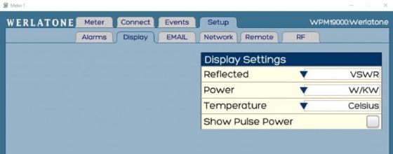
Figure 5
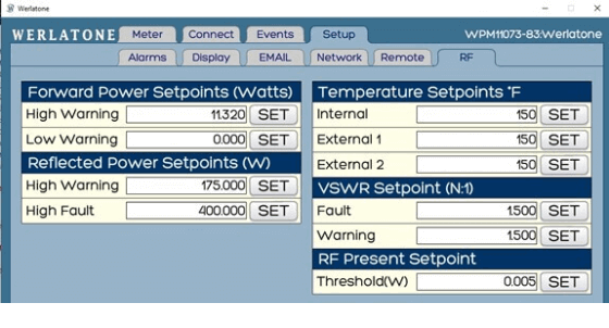
Figure 6
Remote I/O
allows access to several important parameter setings.
- Programming the function of the two on-board relay closures. (Figure 7)
- Full Scale Indication of the Forward and Reflected D.C. sample power indications (normally factory set).
- Configuration of up to four interlock groups. (Figure 7)
RELAY 1
can be programmed as an interlock closure or alarm closure. When set to INTERLOCK, the relay will remain closed as long as the Reflected Power is less than the programmed threshold and the conditions of the enabled interlock group(s) is satisfied.
RELAY 2
can be programmed as a second Interlock. Interlock options include an ALARM RELAY, an RF PRESENT CLOSURE, and an RF PRESENCE THRESHOLD. The RF PRESENCE THRESHOLD can be programmed to engage when RF is below a programmed threshold. This seting is a valuable tool for RF safety plans, allowing remote or local indication of RF Presence.
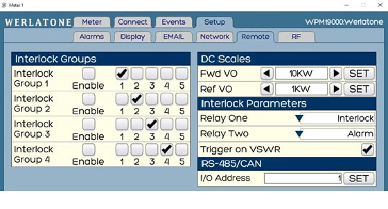
Figure 7
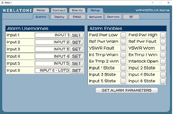
Figure 8
- The Reflected Power sample can detect a threshold dependent on a high reflected power condition. The Power Meter can be programmed to open a relay upon sustained RF fault conditions.
- The relay can be used to interface to a transmitier or power amplifier to turn it off or on for an external alarm.
General Purpose Inputs
with multiple uses. (Figure 8)
- Track Switch Closures (Assign to interlock group).
- Trigger Alarm Relay (Sends email alert).
- RF Presence Status/Alarm (Safety feature).
- Alarm Activated Switch.
- Customer can format Trigger Alarm Relays to issue Alerts via Audio/Visual Indicators, as well as, Email Warnings for Offsite and Remote Users.
Accessories and Current Broadband Products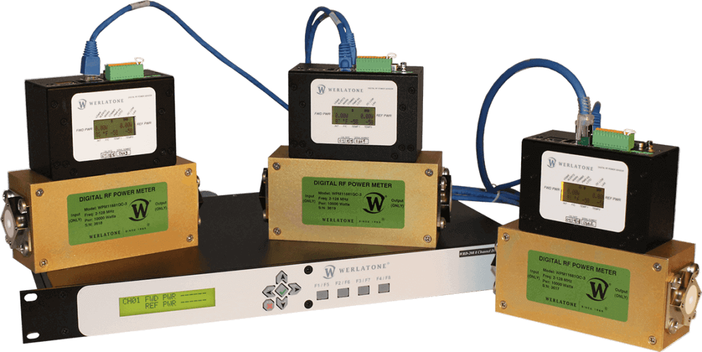

Accessories:
- Single Channel Monitor (1U Rack, Graphical User Interface).
- Four-Channel Monitor (1U Rack, Graphical User Interface).
- Eight-Channel Monitor (1U Rack, Graphical User Interface).
Werlatone Multi-Channel Display Monitors are designed to interface up to eight Digital Power Meters and are capable of monitoring RF antenna and amplifier systems. Our Multi-Channel Displays will monitor Forward and Reflected Power, as well as Load VSWR, and Temperature.
Designed to distribute transmitter interlock control of up to eight transmitters, our Displays are web-enabled for remote display of all parameters and remote control of fault reset.
- Android APP controls remotely and monitors system operation.
- PC-Based Graphical User Interface, Windows XP/7/8/10 compatible.
- Power Meter is SNMP programmable using Customer’s preferred interface. (A LabView Driver is available for LabView Users).
