Coaxial Combiners
Werlatone® Mismatch Tolerant® High Power Broadband RF Combiners & RF Dividers operate into High Load VSWR Conditions, for extended periods, without damage.
When specified, we design our High Power Combiners and RF Dividers to tolerate full input failures on adjacent ports(s).
Choose Filters
FILTERS| Model | Docs | Cart | Type | Frequency (MHz) | Power (Watts CW) | Insertion Loss (dB) | VSWR | Isolation (dB) | Size (Inches) | Interface Conn/Non-Сonn |
|---|---|---|---|---|---|---|---|---|---|---|
| D10421 | Add to Cart | 2-Way RF Combiner | 0.01 - 30 | 25 | 0.4 | 1.35:1 | 20 | 5.0 x 3.0 x 1.5 | Connectorized | |
| D5674 | Add to Cart | 2-Way RF Combiner | 0.01 - 250 | 100 | 1.5 | 1.40:1 | 18 | 7.75 x 6.0 x 3.17 | Connectorized | |
| D10551 | Add to Cart | 2-Way RF Combiner | 0.01 - 400 | 100 | 0.6 | 1.50:1 | 15 | 6.5 x 4.45 x 2.0 | Connectorized | |
| D9161 | Add to Cart | 4-Way RF Combiner | 0.1 - 15 | 100 | 0.25 | 1.30:1 | 20 | 6.0 x 5.0 x 2.0 | Connectorized | |
| D9162 | Add to Cart | 4-Way RF Combiner | 0.1 - 15 | 2500 | 0.35 | 1.30:1 | 18 | 13.0 x 7.25 x 3.59 | Connectorized | |
| D6103 | Add to Cart | 2-Way RF Combiner | 0.1 - 20 | 400 | 0.2 | 1.20:1 | 20 | 7.0 x 3.75 x 2.62 | Connectorized | |
| D5704 | Add to Cart | 4-Way RF Combiner | 0.1 - 30 | 1000 | 0.3 | 1.30:1 | 20 | 7.0 x 5.5 x 2.25 | Connectorized | |
| D10219 | Add to Cart | 2-Way RF Combiner | 0.1 - 80 | 25 | 0.3 | 1.30:1 | 25 | 5.0 x 3.0 x 1.5 | Connectorized | |
| D2426 | Add to Cart | 4-Way RF Combiner | 0.1 - 220 | 300 | 1.7 | 1.35:1 | 20 | 9.0 x 8.0 x 3.6 | Connectorized | |
| D6300 | Add to Cart | 2-Way RF Combiner | 0.1 - 250 | 100 | 0.5 | 1.35:1 | 15 | 6.5 x 4.45 x 2.0 | Connectorized | |
| D9090 | Add to Cart | 2-Way RF Combiner | 0.1 - 250 | 400 | 0.6 | 1.50:1 | 15 | 6.5 x 4.45 x 2.0 | Connectorized | |
| D5025 | Add to Cart | 2-Way RF Combiner | 0.5 - 1 | 100 | 0.15 | 1.20:1 | 25 | 3.0 x 3.0 x 2.25 | Connectorized | |
| D3510 | Add to Cart | 4-Way RF Combiner | 0.5 - 30 | 5 | 0.5 | 1.30:1 | 30 | 3.0 x 3.0 x 2.24 | Connectorized | |
| D5253 | Add to Cart | 2-Way RF Combiner | 1 - 30 | 200 | 0.3 | 1.30:1 | 20 | 3.0 x 3.0 x 2.25 | Connectorized | |
| D5855 | Add to Cart | 4-Way RF Combiner | 1 - 30 | 200 | 0.2 | 1.20:1 | 25 | 6.0 x 5.0 x 2.0 | Connectorized | |
| D8230 | Add to Cart | 4-Way RF Combiner | 1 - 30 | 2500 | 0.2 | 1.15:1 | 30 | 10.5 x 5.4 x 1.28 | Connectorized | |
| D5796 | Add to Cart | 4-Way RF Combiner | 1 - 32 | 400 | 0.3 | 1.25:1 | 20 | 6.0 x 5.0 x 2.0 | Connectorized | |
| D5387 | Add to Cart | 4-Way RF Combiner | 1 - 50 | 1000 | 0.3 | 1.30:1 | 20 | 9.5 x 8.5 x 2.84 | Connectorized | |
| D6283 | Add to Cart | 2-Way RF Combiner | 1 - 50 | 2000 | 0.2 | 1.25:1 | 20 | 7.3 x 5.68 x 3.34 | Connectorized | |
| D8265 | Add to Cart | 2-Way RF Combiner | 1 - 50 | 5000 | 0.3 | 1.25:1 | 20 | 15.50 x 11.75 x 5.25 | Connectorized | |
| D1624 | Add to Cart | 4-Way RF Combiner | 1 - 500 | 100 | 0.8 | 1.40:1 | 25 | 6.0 x 5.0 x 2.25 | Connectorized | |
| D1440 | Add to Cart | 4-Way RF Combiner | 1 - 1000 | 15 | 1.2 | 1.50:1 | 20 | 5.0 x 2.0 x 1.9 | Connectorized | |
| D1572 | Add to Cart | 4-Way RF Combiner | 1 - 1000 | 50 | 1.2 | 1.50:1 | 20 | 6.0 x 5.0 x 2.25 | Connectorized | |
| D9302 | Add to Cart | 2-Way RF Combiner | 1 - 1000 | 100 | 0.7 | 1.40:1 | 15 | 3.0 x 1.6 x 0.8 | Connectorized | |
| D9335 | Add to Cart | 2-Way RF Combiner | 1 - 1000 | 100 | 0.7 | 1.40:! | 15 | 3.0 x 1.6 x 0.8 | Connectorized | |
| D9731 | Add to Cart | 2-Way RF Combiner | 1 - 1000 | 100 | 0.7 | 1.40:1 | 15 | 3.25 x 2.0 x 1.10 | Connectorized | |
| D6183 | Add to Cart | 4-Way RF Combiner | 1 - 1000 | 250 | 1.2 | 1.45:1 | 18 | 8.0 x 6.0 x 2.25 | Connectorized | |
| D9820 | Add to Cart | 6-Way RF Combiner | 1.5 - 30 | 100 | 0.7 | 1.35:1 | 25 | 7.0 x 5.0 x 2.0 | Connectorized | |
| D5312 | Add to Cart | 2-Way RF Combiner | 1.5 - 30 | 500 | 0.2 | 1.30:1 | 20 | 3.0 x 3.0 x 2.24 | Connectorized | |
| D2076 | Add to Cart | 2-Way RF Combiner | 1.5 - 30 | 3000 | 0.1 | 1.25:1 | 22 | 7.0 x 3.75 x 2.62 | Connectorized | |
| D5807 | Add to Cart | 4-Way RF Combiner | 1.5 - 30 | 4000 | 0.25 | 1.20:1 | 25 | 13.0 x 11.0 x 3.7 | Connectorized | |
| D6846 | Add to Cart | 6-Way RF Combiner | 1.5 - 30 | 4000 | 0.35 | 1.35:1 | 20 | 19.0 x 17.0 x 5.22 | Connectorized | |
| D2075 | Add to Cart | 2-Way RF Combiner | 1.5 - 30 | 6000 | 0.2 | 1.25:1 | 20 | 15.50 x 11.75 x 5.25 | Connectorized | |
| D6046 | Add to Cart | 2-Way RF Combiner | 1.5 - 30 | 10000 | 0.2 | 1.25:1 | 20 | 15.50 x 11.75 x 5.25 | Connectorized | |
| D8969 | Add to Cart | 2-Way RF Combiner | 1.5 - 30 | 12500 | 0.2 | 1.25:1 | 20 | 17.0 x 17.0 x 8.0 | Connectorized | |
| D6139 | Add to Cart | 4-Way RF Combiner | 1.5 - 32 | 5000 | 0.25 | 1.25:1 | 20 | 13.0 x 11.0 x 5.0 | Connectorized | |
| D6774 | Add to Cart | 4-Way RF Combiner | 1.5 - 32 | 20000 | 0.3 | 1.20:1 | 20 | 21.0 x 17.25 x 11.0 | Connectorized | |
| D10386 | Add to Cart | 2-Way RF Combiner | 1.5 - 40 | 5000 | 0.3 | 1.25:1 | 20 | 13.0 x 11.0 x 5.0 | Connectorized | |
| D5775 | Add to Cart | 4-Way RF Combiner | 1.5 - 50 | 3000 | 0.2 | 1.15:1 | 25 | 13.0 x 11.0 x 3.7 | Connectorized | |
| D9645 | Add to Cart | 4-Way RF Combiner | 2 - 30 | 4000 | 0.35 | 1.20:1 | 20 | 20.25 x 16.89 x 5.22 | Connectorized | |
| D2551 | Add to Cart | 2-Way RF Combiner | 2 - 32 | 1000 | 0.1 | 1.30:1 | 20 | 3.0 x 3.0 x 2.24 | Connectorized | |
| D9589 | Add to Cart | 2-Way RF Combiner | 2 - 32 | 1000 | 0.1 | 1.30:1 | 20 | 3.0 x 3.0 x 2.24 | Connectorized | |
| D5889 | Add to Cart | 2-Way RF Combiner | 2 - 50 | 200 | 0.2 | 1.30:1 | 20 | 3.0 x 3.0 x 2.25 | Connectorized | |
| D7685 | Add to Cart | 4-Way RF Combiner | 2 - 100 | 2500 | 0.5 | 1.30:1 | 20 | 15.0 x 13.0 x 5.5 | Connectorized | |
| D1635 | Add to Cart | 2-Way RF Combiner | 2 - 220 | 200 | 0.4 | 1.30:1 | 20 | 3.0 x 3.0 x 2.25 | Connectorized | |
| D8976 | Add to Cart | 2-Way RF Combiner | 2 - 220 | 400 | 0.4 | 1.30:1 | 20 | 6.5 x 4.45 x 2.0 | Connectorized | |
| D10210 | Add to Cart | 4-Way RF Combiner | 5 - 20 | 1000 | 0.3 | 1.30:1 | 20 | 6.0 x 5.0 x 2.0 | Connectorized | |
| D10458 | Add to Cart | 2-Way RF Combiner | 5 - 40 | 2000 | 0.3 | 1.25:1 | 22 | 7.0 x 3.75 x 2.62 | Connectorized | |
| D6516 | Add to Cart | 4-Way RF Combiner | 10 - 100 | 25 | 0.5 | 1.20:1 | 20 | 3.0 x 3.0 x 0.8 | Connectorized | |
| D7312 | Add to Cart | 4-Way RF Combiner | 10 - 100 | 100 | 0.35 | 1.25:1 | 20 | 3.0 x 3.0 x 0.8 | Connectorized | |
| D9008 | Add to Cart | 4-Way RF Combiner | 10 - 100 | 200 | 0.4 | 1.30:1 | 20 | 6.0 x 5.0 x 2.0 | Connectorized | |
| D6517 | Add to Cart | 4-Way RF Combiner | 10 - 100 | 500 | 0.4 | 1.30:1 | 20 | 6.0 x 5.0 x 2.0 | Connectorized | |
| D6448 | Add to Cart | 4-Way RF Combiner | 10 - 100 | 1000 | 0.4 | 1.30:1 | 20 | 6.0 x 5.0 x 2.0 | Connectorized | |
| D10074 | Add to Cart | 4-Way RF Combiner | 10 - 100 | 5000 | 0.3 | 1.25:1 | 20 | 14.375 x 12.0 x 5.0 | Connectorized | |
| D3857 | Add to Cart | 4-Way RF Combiner | 10 - 100 | 5000 | 0.6 | 1.40:1 | 18 | 18.0 x 17.0 x 5.0 | Connectorized | |
| D6037 | Add to Cart | 2-Way RF Combiner | 10 - 140 | 400 | 0.3 | 1.35:1 | 20 | 6.5 x 4.45 x 2.0 | Connectorized | |
| D9079 | Add to Cart | 8-Way RF Combiner | 10 - 165 | 800 | 0.65 | 1.50:1 | 20 | 17.0 x 7.0 x 2.25" | Connectorized | |
| D9206 | Add to Cart | 5-Way RF Combiner | 10 - 175 | 100 | 0.8 | 1.50:1 | 15 | 6.75 x 5.0 x 2.25 | Connectorized | |
| D6530 | Add to Cart | 4-Way RF Combiner | 10 - 500 | 100 | 0.6 | 1.25:1 | 20 | 3.0 x 3.0 x 0.8 | Connectorized | |
| D5687 | Add to Cart | 2-Way RF Combiner | 10 - 500 | 200 | 0.5 | 1.40:1 | 20 | 5.0 x 3.5 x 2.0 | Connectorized | |
| D5607 | Add to Cart | 2-Way RF Combiner | 10 - 500 | 500 | 0.4 | 1.35:1 | 20 | 6.5 x 4.45 x 2.0 | Connectorized | |
| D6163 | Add to Cart | 2-Way RF Combiner | 10 - 1000 | 25 | 0.75 | 1.35:1 | 20 | 3.0 x 1.6 x 0.8 | Connectorized | |
| D6233 | Add to Cart | 2-Way RF Combiner | 10 - 1000 | 25 | 0.75 | 1.35:1 | 20 | 3.25 x 2.0 x 1.10 | Connectorized | |
| D5251 | Add to Cart | 4-Way RF Combiner | 13 - 14 | 2000 | 0.3 | 1.30:1 | 20 | 9.5 x 8.5 x 3.0 | Connectorized | |
| D6251 | Add to Cart | 4-Way RF Combiner | 13 - 15 | 10000 | 0.25 | 1.20:1 | 25 | 13.0 x 11.0 x 5.0 | Connectorized | |
| D10484 | Add to Cart | 4-Way RF Combiner | 15 - 500 | 200 | 0.5 | 1.40:1 | 20 | 5.1 x 5.0 x 1.5 | Connectorized | |
| D5486 | Add to Cart | 4-Way RF Combiner | 18 - 115 | 400 | 0.4 | 1.25:1 | 20 | 6.0 x 5.0 x 2.0 | Connectorized | |
| D5489 | Add to Cart | 4-Way RF Combiner | 18 - 115 | 3000 | 0.3 | 1.25:1 | 20 | 13.0 x 11.0 x 3.7 | Connectorized | |
| D5491 | Add to Cart | 4-Way RF Combiner | 18 - 115 | 7000 | 0.3 | 1.25:1 | 20 | 14.75 x 12.0 x 5.0 | Connectorized | |
| D8123 | Add to Cart | 2-Way RF Combiner | 20 - 60 | 5000 | 0.2 | 1.25:1 | 20 | 15.50 x 11.75 x 5.25 | Connectorized | |
| D5786 | Add to Cart | 2-Way RF Combiner | 20 - 100 | 200 | 0.25 | 1.30:1 | 20 | 3.0 x 3.0 x 2.25 | Connectorized | |
| D1994 | Add to Cart | 2-Way RF Combiner | 20 - 100 | 600 | 0.3 | 1.30:1 | 20 | 5.0 x 3.0 x 2.3 | Connectorized | |
| D7965 | Add to Cart | 2-Way RF Combiner | 20 - 100 | 1200 | 0.2 | 1.20:1 | 20 | 7.0 x 4.0 x 1.62 | Connectorized | |
| D7897 | Add to Cart | 2-Way RF Combiner | 20 - 100 | 1600 | 0.2 | 1.20:1 | 20 | 7.0 x 3.75 x 2.62 | Connectorized | |
| D8959 | Add to Cart | 4-Way RF Combiner | 20 - 100 | 1750 | 0.3 | 1.30:1 | 23 | 9.4 x 8.4 x 2.25 | Connectorized | |
| D9923 | Add to Cart | 4-Way RF Combiner | 20 - 100 | 3000 | 0.3 | 1.25:1 | 20 | 13.0 x 11.0 x 3.7 | Connectorized | |
| D6717 | Add to Cart | 3-Way RF Combiner | 20 - 130 | 100 | 0.35 | 1.30:1 | 18 | 5.0 x 3.0 x 2.25 | Connectorized | |
| D8110 | Add to Cart | 4-Way RF Combiner | 20 - 130 | 600 | 0.4 | 1.25:1 | 20 | 6.0 x 4.5 x 2.0 | Connectorized | |
| D8146 | Add to Cart | 3-Way RF Combiner | 20 - 130 | 1500 | 0.35 | 1.40:1 | 18 | 13.0 x 6.0 x 2.75 | Connectorized | |
| D10302 | Add to Cart | 4-Way RF Combiner | 20 - 130 | 2000 | 0.4 | 1.30:1 | 20 | 13.0 x 7.25 x 3.59 | Connectorized | |
| D10360 | Add to Cart | 4-Way RF Combiner | 20 - 130 | 8000 | 0.3 | 1.25:1 | 20 | 14.75 x 12.0 x 5.0 | Connectorized | |
| D9221 | Add to Cart | 4-Way RF Combiner | 20 - 130 | 10000 | 0.3 | 1.25:1 | 20 | 14.75 x 12.0 x 5.0 | Connectorized | |
| D10696 | Add to Cart | 2-Way RF Combiner | 20 - 200 | 1000 | 0.5 | 1.35:1 | 20 | 6.5 x 6.25 x 2.25 | Connectorized | |
| D8803 | Add to Cart | 4-Way RF Combiner | 20 - 300 | 1750 | 0.5 | 1.30:1 | 18 | 9.4 x 8.4 x 2.25 | Connectorized | |
| D6253 | Add to Cart | 2-Way RF Combiner | 20 - 500 | 25 | 0.5 | 1.35:1 | 25 | 3.0 x 1.6 x 0.8 | Connectorized | |
| D7572 | Add to Cart | 2-Way RF Combiner | 20 - 500 | 25 | 0.5 | 1.35:1 | 25 | 3.25 x 2.0 x 1.10 | Connectorized | |
| D8444 | Add to Cart | 2-Way RF Combiner | 20 - 500 | 25 | 0.5 | 1.30:1 | 20 | 2.1 x 1.3 x 0.8 | Connectorized | |
| D6193 | Add to Cart | 4-Way RF Combiner | 20 - 500 | 25 | 0.65 | 1.30:1 | 20 | 3.0 x 3.0 x 0.8 | Connectorized | |
| D7974 | Add to Cart | 2-Way RF Combiner | 20 - 500 | 50 | 0.35 | 1.30:1 | 20 | 3.0 x 1.6 x 0.8 | Connectorized | |
| D7975 | Add to Cart | 2-Way RF Combiner | 20 - 500 | 50 | 0.35 | 1.30:1 | 20 | 3.25 x 2.0 x 1.10 | Connectorized | |
| D6405 | Add to Cart | 4-Way RF Combiner | 20 - 500 | 50 | 0.65 | 1.30:1 | 20 | 3.0 x 3.0 x 0.8 | Connectorized | |
| D7171 | Add to Cart | 2-Way RF Combiner | 20 - 500 | 100 | 0.3 | 1.30:1 | 20 | 2.45 x 2.0 x 0.67 | Connectorized | |
| D7562 | Add to Cart | 2-Way RF Combiner | 20 - 500 | 100 | 0.3 | 1.30:1 | 20 | 2.45 x 2.0 x 0.91 | Connectorized | |
| D7587 | Add to Cart | 4-Way RF Combiner | 20 - 500 | 100 | 0.5 | 1.30:1 | 20 | 5.09 x 2.3 x 1.0 | Connectorized | |
| D7896 | Add to Cart | 2-Way RF Combiner | 20 - 500 | 200 | 0.35 | 1.30:1 | 20 | 3.17 x 2.0 x 0.91 | Connectorized | |
| D5816 | Add to Cart | 4-Way RF Combiner | 20 - 500 | 200 | 0.5 | 1.35:1 | 20 | 5.1 x 5.0 x 1.5 | Connectorized | |
| D5829 | Add to Cart | 8-Way RF Combiner | 20 - 500 | 400 | 0.75 | 1.40:1 | 20 | 12.0 x 7.75 x 2.25 | Connectorized | |
| D7105 | Add to Cart | 2-Way RF Combiner | 20 - 500 | 500 | 0.35 | 1.30:1 | 20 | 3.30 x 2.65 x 1.0 | Connectorized | |
| D5612 | Add to Cart | 4-Way RF Combiner | 20 - 500 | 500 | 0.7 | 1.40:1 | 20 | 7.5 x 7.0 x 2.25 | Connectorized | |
| D9891 | Add to Cart | 2-Way RF Combiner | 20 - 500 | 1000 | 0.8 | 1.40:1 | 18 | 6.5 x 6.25 x 2.25 | Connectorized | |
| D5575 | Add to Cart | 4-Way RF Combiner | 20 - 500 | 1000 | 0.7 | 1.40:1 | 18 | 7.5 x 7.0 x 2.25 | Connectorized | |
| D10348 | Add to Cart | 4-Way RF Combiner | 20 - 500 | 1200 | 0.7 | 1.40:1 | 18 | 7.5 x 7.0 x 2.25 | Connectorized | |
| D10907 | Add to Cart | 4-Way RF Combiner | 20 - 500 | 1300 | 0.5 | 1.35:1 | 15 | 5.7 x 4.7 x 1.75 | Connectorized | |
| D5576 | Add to Cart | 2-Way RF Combiner | 20 - 500 | 1500 | 0.5 | 1.35:1 | 15 | 8.0 x 7.5 x 4.5 | Connectorized | |
| D9598 | Add to Cart | 2-Way RF Combiner | 20 - 520 | 200 | 0.35 | 1.30:1 | 20 | 3.30 x 2.65 x 1.0 | Connectorized | |
| D9605 | Add to Cart | 2-Way RF Combiner | 20 - 520 | 2000 | 0.6 | 1.35:1 | 15 | 7.75 x 7.0 x 2.6 | Connectorized | |
| D8632 | Add to Cart | 2-Way RF Combiner | 20 - 1000 | 50 | 0.7 | 1.40:1 | 20 | 2.2 x 1.5 x 0.9 | Connectorized | |
| D7728 | Add to Cart | 2-Way RF Combiner | 20 - 1000 | 100 | 0.75 | 1.30:1 | 18 | 3.0 x 1.6 x 0.8 | Connectorized | |
| D7745 | Add to Cart | 2-Way RF Combiner | 20 - 1000 | 100 | 0.85 | 1.30:1 | 18 | 3.25 x 2.0 x 1.10 | Connectorized | |
| D8300 | Add to Cart | 2-Way RF Combiner | 20 - 1000 | 100 | 0.5 | 1.35:1 | 20 | 2.45 x 2.0 x 0.91 | Connectorized | |
| D8544W | Add to Cart | 2-Way RF Combiner | 20 - 1000 | 100 | 0.5 | 1.35:1 | 18 | 2.85 x 2.5 x 1.0 | Connectorized | |
| D7365 | Add to Cart | 4-Way RF Combiner | 20 - 1000 | 100 | 0.75 | 1.35:1 | 20 | 5.09 x 2.3 x 1.0 | Connectorized | |
| D8633 | Add to Cart | 2-Way RF Combiner | 20 - 1000 | 150 | 0.6 | 1.40:1 | 20 | 2.7 x 2.2 x 0.91 | Connectorized | |
| D9317 | Add to Cart | 4-Way RF Combiner | 20 - 1000 | 200 | 0.7 | 1.40:1 | 15 | 3.76 x 3.76 x 0.9 | Connectorized | |
| D7439 | Add to Cart | 4-Way RF Combiner | 20 - 1000 | 250 | 0.75 | 1.35:1 | 18 | 5.1 x 5.0 x 1.5 | Connectorized | |
| D8682 | Add to Cart | 2-Way RF Combiner | 20 - 1000 | 500 | 0.7 | 1.35:1 | 15 | 5.20 x 2.65 x 1.8 | Connectorized | |
| D8851W | Add to Cart | 2-Way RF Combiner | 20 - 1000 | 500 | 0.7 | 1.35:1 | 15 | 5.62 x 3.07 x 1.8 | Connectorized | |
| D9048 | Add to Cart | 4-Way RF Combiner | 20 - 1000 | 500 | 0.6 | 1.35:1 | 17 | 5.0 x 4.7 x 1.4 | Connectorized | |
| D10249 | Add to Cart | 2-Way RF Combiner | 20 - 1000 | 1000 | 0.8 | 1.40:1 | 18 | 6.5 x 6.25 x 2.25 | Connectorized | |
| D9264 | Add to Cart | 2-Way RF Combiner | 20 - 1000 | 1000 | 0.8 | 1.40:1 | 18 | 6.5 x 6.25 x 2.25 | Connectorized | |
| D9075 | Add to Cart | 4-Way RF Combiner | 20 - 1000 | 1000 | 0.65 | 1.35:1 | 15 | 5.7 x 4.7 x 1.75 | Connectorized | |
| D8339 | Add to Cart | 2-Way RF Combiner | 20 - 2000 | 5 | 1.2 | 1.70:1 | 15 | 3.0 x 1.6 x 0.8 | Connectorized | |
| D8341 | Add to Cart | 2-Way RF Combiner | 20 - 2000 | 20 | 1.2 | 1.70:1 | 15 | 3.0 x 1.6 x 0.8 | Connectorized | |
| D9980 | Add to Cart | 3-Way RF Combiner | 20 - 2500 | 50 | 1.0 | 1.30:1 | Non-Isolated | 3.35 x 2.75 x 0.85 | Connectorized | |
| D9310 | Add to Cart | 4-Way RF Combiner | 20 - 3000 | 50 | 1.2 | 1.50:1 | 15 | 3.35 x 2.75 x 0.85 | Connectorized | |
| D9649 | Add to Cart | 4-Way RF Combiner | 20 - 4000 | 50 | 1.5 | 1.70:1 | 12 | 3.35 x 2.75 x 0.85 | Connectorized | |
| D10267 | Add to Cart | 4-Way RF Combiner | 22 - 32 | 10000 | 0.25 | 1.20:1 | 25 | 13.0 x 11.0 x 5.0 | Connectorized | |
| D8032 | Add to Cart | 3-Way RF Combiner | 25 - 450 | 200 | 0.75 | 1.35:1 | 20 | 5.4 x 3.0 x 1.0 | Connectorized | |
| D5839 | Add to Cart | 2-Way RF Combiner | 30 - 88 | 100 | 0.35 | 1.35:1 | 35 | 3.30 x 2.65 x 1.0 | Connectorized | |
| D6617 | Add to Cart | 2-Way RF Combiner | 30 - 88 | 200 | 0.25 | 1.25:1 | 30 | 3.0 x 3.0 x 2.25 | Connectorized | |
| D6001 | Add to Cart | 2-Way RF Combiner | 30 - 88 | 300 | 0.2 | 1.30:1 | 20 | 3.0 x 3.0 x 2.25 | Connectorized | |
| D5770 | Add to Cart | 4-Way RF Combiner | 30 - 90 | 20 | 0.3 | 1.30:1 | 20 | 6.0 x 5.0 x 2.0 | Connectorized | |
| D5919 | Add to Cart | 4-Way RF Combiner | 30 - 90 | 40 | 0.3 | 1.30:1 | 20 | 6.0 x 5.0 x 2.0 | Connectorized | |
| D8496 | Add to Cart | 2-Way RF Combiner | 30 - 90 | 50 | 0.25 | 1.30:1 | 25 | 3.4 x 3.4 x 2.25 | Connectorized | |
| D5920 | Add to Cart | 4-Way RF Combiner | 30 - 90 | 150 | 0.3 | 1.30:1 | 20 | 6.0 x 5.0 x 2.0 | Connectorized | |
| D5778 | Add to Cart | 4-Way RF Combiner | 30 - 90 | 5000 | 0.3 | 1.30:1 | 20 | 18.0 x 17.0 x 5.0 | Connectorized | |
| D5747 | Add to Cart | 2-Way RF Combiner | 30 - 400 | 300 | 0.4 | 1.35:1 | 20 | 6.5 x 4.45 x 2.0 | Connectorized | |
| D7070 | Add to Cart | 3-Way RF Combiner | 30 - 500 | 100 | 0.75 | 1.35:1 | 20 | 5.4 x 3.0 x 1.31 | Connectorized | |
| D10811 | Add to Cart | 3-Way RF Combiner | 30 - 500 | 250 | 0.85 | 1.50:1 | 20 | 12.0 x 8.0 x 2.75 | Connectorized | |
| D9866 | Add to Cart | 3-Way RF Combiner | 30 - 500 | 750 | 1.0 | 1.50:1 | 20 | 12.0 x 8.0 x 2.75 | Connectorized | |
| D8832 | Add to Cart | 2-Way RF Combiner | 30 - 512 | 650 | 0.50 | 1.35:1 | 20 | 6.5 x 4.45 x 2.0 | Connectorized | |
| D8907 | Add to Cart | 4-Way RF Combiner | 30 - 520 | 1000 | 0.70 | 1.40:1 | 18 | 7.5 x 7.0 x 1.75 | Connectorized | |
| D9585 | Add to Cart | 2-Way RF Combiner | 30 - 520 | 2000 | 0.6 | 1.35:1 | 15 | 7.75 x 7.0 x 2.6 | Connectorized | |
| D8607 | Add to Cart | 2-Way RF Combiner | 30 - 600 | 200 | 0.4 | 1.30:1 | 25 | 3.85 x 3.8 x 1.11 | Connectorized | |
| D8607W | Add to Cart | 2-Way RF Combiner | 30 - 600 | 200 | 0.4 | 1.30:1 | 25 | 3.85 x 3.8 x 1.11 | Connectorized | |
| D2413 | Add to Cart | 4-Way RF Combiner | 50 - 200 | 4000 | 0.4 | 1.30:1 | 20 | 18.0 x 17.0 x 5.0 | Connectorized | |
| D3821 | Add to Cart | 2-Way RF Combiner | 77 - 2200 | 100 | 1.0 | 1.50:1 | Non-Isolated | 12.0 x 7.8 x 1.78 | Connectorized | |
| D5875 | Add to Cart | 4-Way RF Combiner | 80 - 1000 | 150 | 0.75 | 1.30:1 | Non-Isolated | 7.55 x 8.38 x 1.5 | Connectorized | |
| D3806 | Add to Cart | 2-Way RF Combiner | 80 - 1000 | 500 | 0.5 | 1.40:1 | Non-Isolated | 14.4 x 8.11 x 1.78 | Connectorized | |
| D10856 | Add to Cart | 4-Way RF Combiner | 80 - 1000 | 750 | 0.6 | 1.35:1 | Partially Isolated | 5.0 x 4.7 x 1.4 | Connectorized | |
| D9002 | Add to Cart | 4-Way RF Combiner | 80 - 1000 | 750 | 0.6 | 1.35:1 | 17 | 5.0 x 4.7 x 1.4 | Connectorized | |
| D9197 | Add to Cart | 4-Way RF Combiner | 80 - 1000 | 750 | 0.65 | 1.35:1 | 17 | 5x4.7x1.4 | Connectorized | |
| D8383 | Add to Cart | 2-Way RF Combiner | 80 - 1000 | 1000 | 0.5 | 1.40:1 | 18 | 13.0 x 7.0 x 2.22 | Connectorized | |
| D9440 | Add to Cart | 4-Way RF Combiner | 80 - 1000 | 1000 | 0.65 | 1.35:1 | 15 | 5.7 x 4.7 x 1.75 | Connectorized | |
| D10830 | Add to Cart | 2-Way RF Combiner | 80 - 1000 | 2000 | 0.5 | 1.30:1 | Non-Isolated | 5.5 x 5.0 x 1.71 | Connectorized | |
| D6129 | Add to Cart | 2-Way RF Combiner | 80 - 1000 | 2000 | 0.5 | 1.40:1 | 15 | 11.75 x 10.0 x 2.25 | Connectorized | |
| D10629 | Add to Cart | 4-Way RF Combiner | 80 - 1000 | 2000 | 0.65 | 1.35:1 | 15 | 5.7 x 4.7 x 1.75 | Connectorized | |
| D2873 | Add to Cart | 4-Way RF Combiner | 88 - 108 | 100 | 0.3 | 1.30:1 | 20 | 6.0 x 3.0 x 2.25 | Connectorized | |
| D2888 | Add to Cart | 4-Way RF Combiner | 88 - 108 | 600 | 0.2 | 1.30:1 | 20 | 6.0 x 5.0 x 2.12 | Connectorized | |
| D4034 | Add to Cart | 2-Way RF Combiner | 88 - 108 | 1000 | 0.3 | 1.25:1 | 20 | 6.0 x 5.0 x 2.5 | Connectorized | |
| D2889 | Add to Cart | 4-Way RF Combiner | 88 - 108 | 2500 | 0.3 | 1.30:1 | 20 | 16.87 x 8.5 x 2.09 | Connectorized | |
| D6100 | Add to Cart | 2-Way RF Combiner | 100 - 500 | 25 | 0.5 | 1.35:1 | 25 | 3.0 x 1.6 x 0.8 | Connectorized | |
| D7626 | Add to Cart | 2-Way RF Combiner | 100 - 500 | 25 | 0.50 | 1.35:1 | 25 | 3.25 x 2.0 x 1.10 | Connectorized | |
| D6000 | Add to Cart | 4-Way RF Combiner | 100 - 500 | 25 | 0.65 | 1.30:1 | 20 | 3.0 x 3.0 x 0.8 | Connectorized | |
| D8296 | Add to Cart | 4-Way RF Combiner | 100 - 500 | 25 | 0.65 | 1.30:1 | 20 | 4.2 x 3.0 x 1.1 | Connectorized | |
| D6760 | Add to Cart | 2-Way RF Combiner | 100 - 500 | 50 | 0.5 | 1.35:1 | 20 | 3.0 x 1.6 x 0.8 | Connectorized | |
| D6738 | Add to Cart | 4-Way RF Combiner | 100 - 500 | 50 | 0.65 | 1.30:1 | 20 | 3.0 x 3.0 x 0.8 | Connectorized | |
| D7142 | Add to Cart | 2-Way RF Combiner | 100 - 500 | 100 | 0.40 | 1.25:1 | 20 | 4.4 x 4.3 x 1.29 | Connectorized | |
| D7438 | Add to Cart | 3-Way RF Combiner | 100 - 500 | 100 | 0.75 | 1.35:1 | 20 | 5.4 x 3.0 x 1.31 | Connectorized | |
| D10508W | Add to Cart | 2-Way RF Combiner | 100 - 500 | 200 | 0.4 | 1.25:1 | 20 | 4.4 x 4.3 x 1.29 | Connectorized | |
| D10905 | Add to Cart | 2-Way RF Combiner | 100 - 500 | 500 | 0.35 | 1.30:1 | 20 | 3.30 x 2.65 x 1.0 | Connectorized | |
| D5800 | Add to Cart | 2-Way RF Combiner | 100 - 500 | 500 | 0.4 | 1.35:1 | 20 | 6.5 x 4.5 x 2.0 | Connectorized | |
| D5400 | Add to Cart | 4-Way RF Combiner | 100 - 500 | 500 | 0.5 | 1.40:1 | 20 | 7.5 x 7.0 x 2.25 | Connectorized | |
| D9258 | Add to Cart | 4-Way RF Combiner | 100 - 500 | 500 | 0.4 | 1.25:1 | 20 | 5.0 x 4.7 x 1.4 | Connectorized | |
| D5900 | Add to Cart | 2-Way RF Combiner | 100 - 500 | 1000 | 0.25 | 1.20:1 | 23 | 7.5 x 7.0 x 2.0 | Connectorized | |
| D5300 | Add to Cart | 4-Way RF Combiner | 100 - 500 | 1200 | 0.5 | 1.40:1 | 20 | 7.5 x 7.0 x 2.25 | Connectorized | |
| D5700 | Add to Cart | 2-Way RF Combiner | 100 - 500 | 1500 | 0.3 | 1.30:1 | 20 | 13.0 x 7.0 x 2.25 | Connectorized | |
| D6078 | Add to Cart | 2-Way RF Combiner | 100 - 500 | 2000 | 0.25 | 1.20:1 | 20 | 13.0 x 7.0 x 2.25 | Connectorized | |
| D1990 | Add to Cart | 4-Way RF Combiner | 100 - 1000 | 25 | 0.7 | 1.50:1 | 20 | 5.0 x 2.0 x 1.89 | Connectorized | |
| D1969 | Add to Cart | 4-Way RF Combiner | 100 - 1000 | 100 | 0.6 | 1.50:1 | 20 | 6.0 x 5.0 x 2.25 | Connectorized | |
| D5517 | Add to Cart | 4-Way RF Combiner | 100 - 1000 | 250 | 0.85 | 1.50:1 | 15 | 14.7 x 11.4 x 2.5 | Connectorized | |
| D9422 | Add to Cart | 8-Way RF Combiner | 120 - 122 | 200 | 0.6 | 1.25:1 | 20 | 10.0 x 8.0 x 2.25 | Connectorized | |
| D2542 | Add to Cart | 2-Way RF Combiner | 120 - 470 | 100 | 0.3 | 1.35:1 | Non-Isolated | 2.5 x 1.75 x 1.5 | Connectorized | |
| D7801 | Add to Cart | 8-Way RF Combiner | 121 - 124 | 75 | 0.75 | 1.25:1 | 20 | 10.0 x 8.0 x 2.25 | Connectorized | |
| D8301 | Add to Cart | 2-Way RF Combiner | 121 - 124 | 500 | 0.25 | 1.20:1 | 20 | 4.0 x 2.0 x 1.5 | Connectorized | |
| D7743 | Add to Cart | 16-Way RF Combiner | 125 - 128 | 400 | 0.85 | 1.40:1 | 20 | 12.0 x 12.0 x 4.0 | Connectorized | |
| D9913 | Add to Cart | 4-Way RF Combiner | 127 - 128 | 500 | 0.4 | 1.25:1 | 20 | 6.0 x 5.0 x 2.25 | Connectorized | |
| D9579 | Add to Cart | 4-Way RF Combiner | 136 - 174 | 80 | 0.35 | 1.20:1 | 20 | 4.0 x 3.75 x 1.39 | Connectorized | |
| D10271 | Add to Cart | 2-Way RF Combiner | 140 - 180 | 500 | 0.4 | 1.30:1 | Non-Isolated | 6.0 x 5.0 x 1.06 | Connectorized | |
| D7007 | Add to Cart | 4-Way RF Combiner | 150 - 174 | 200 | 0.35 | 1.25:1 | 20 | 4.75 x 3.0 x 1.2 | Connectorized | |
| D6295 | Add to Cart | 2-Way RF Combiner | 150 - 500 | 100 | 0.3 | 1.30:1 | Non-Isolated | 2.5 x 1.75 x 1.5 | Connectorized | |
| D5877 | Add to Cart | 2-Way RF Combiner | 150 - 1000 | 350 | 0.5 | 1.30:1 | Non-Isolated | 8.38 x 7.55 x 1.55 | Connectorized | |
| D5876 | Add to Cart | 3-Way RF Combiner | 150 - 1000 | 350 | 0.65 | 1.30:1 | Non-Isolated | 8.38 x 7.55 x 1.50 | Connectorized | |
| D5944 | Add to Cart | 4-Way RF Combiner | 150 - 1000 | 350 | 0.7 | 1.30:1 | Non-Isolated | 8.38 x 7.55 x 1.50 | Connectorized | |
| D9423 | Add to Cart | 8-Way RF Combiner | 169 - 171 | 200 | 0.5 | 1.25:1 | 20 | 10.0 x 8.0 x 2.25 | Connectorized | |
| D3030 | Add to Cart | 2-Way RF Combiner | 200 - 400 | 500 | 0.25 | 1.40:1 | 20 | 6.0 x 3.0 x 2.24 | Connectorized | |
| D6386 | Add to Cart | 4-Way RF Combiner | 200 - 1000 | 250 | 0.5 | 1.30:1 | 18 | 13.0 x 7.0 x 2.5 | Connectorized | |
| D9257 | Add to Cart | 4-Way RF Combiner | 200 - 1000 | 500 | 0.65 | 1.35:1 | 17 | 5.0 x 4.7 x 1.4 | Connectorized | |
| D9416 | Add to Cart | 4-Way RF Combiner | 200 - 1000 | 500 | 0.65 | 1.35:1 | 17 | 5.0 x 4.7 x 1.4 | Connectorized | |
| D10854 | Add to Cart | 4-Way RF Combiner | 200 - 1000 | 1200 | 0.65 | 1.35:1 | 15 | 5.7 x 4.7 x 1.75 | Connectorized | |
| D7885 | Add to Cart | 2-Way RF Combiner | 200 - 2500 | 200 | 0.65 | 1.40:1 | 15 | 7.2 x 1.6 x 1.1 | Connectorized | |
| D5268 | Add to Cart | 2-Way RF Combiner | 225 - 400 | 200 | 0.3 | 1.35:1 | 20 | 4.0 x 2.0 x 1.5 | Connectorized | |
| D9610 | Add to Cart | 2-Way RF Combiner | 225 - 400 | 200 | 0.3 | 1.30:1 | 25 | 3.30 x 2.65 x 1.0 | Connectorized | |
| D6357 | Add to Cart | 2-Way RF Combiner | 225 - 400 | 400 | 0.3 | 1.30:1 | 20 | 4.0 x 4.0 x 1.12 | Connectorized | |
| D5809 | Add to Cart | 4-Way RF Combiner | 225 - 400 | 400 | 0.4 | 1.30:1 | 20 | 7.5 x 7.0 x 2.25 | Connectorized | |
| D7044 | Add to Cart | 4-Way RF Combiner | 290 - 300 | 200 | 0.4 | 1.30:1 | 20 | 6.0 x 5.0 x 2.25 | Connectorized | |
| D6861 | Add to Cart | 8-Way RF Combiner | 290 - 300 | 200 | 0.5 | 1.25:1 | 20 | 10.0 x 8.0 x 2.25 | Connectorized | |
| D8271 | Add to Cart | 8-Way RF Combiner | 290 - 300 | 200 | 0.65 | 1.25:1 | 20 | 10.0 x 8.0 x 2.25 | Connectorized | |
| D7167 | Add to Cart | 16-Way RF Combiner | 290 - 300 | 400 | 0.65 | 1.30:1 | 20 | 12.0 x 12.0 x 4.0 | Connectorized | |
| D10363 | Add to Cart | 4-Way RF Combiner | 290 - 320 | 400 | 0.3 | 1.20:1 | 25 | 7.5 x 7.0 x 2.25 | Connectorized | |
| D9816 | Add to Cart | 8-Way RF Combiner | 330 - 530 | 10000 | 0.25 | 1.30:1 | Non-Isolated | Radial | Connectorized | |
| D6140DC | Add to Cart | 2-Way RF Combiner | 380 - 420 | 50 | 0.2 | 1.30:1 | 3.75 x 3.0 x 1.5 | Connectorized | ||
| D7169 | Add to Cart | 8-Way RF Combiner | 390 - 400 | 200 | 0.5 | 1.25:1 | 20 | 10.0 x 8.0 x 2.25 | Connectorized | |
| D7977 | Add to Cart | 16-Way RF Combiner | 398 - 402 | 400 | 0.5 | 1.30:1 | 20 | 14.0 x 12.0 x 5.0 | Connectorized | |
| D7976 | Add to Cart | 8-Way RF Combiner | 398 - 402 | 400 | 0.5 | 1.25:1 | 20 | 10.0 x 8.0 x 2.25 | Connectorized | |
| D8066 | Add to Cart | 4-Way RF Combiner | 398 - 402 | 1000 | 0.4 | 1.30:1 | 20 | 6.0 x 5.0 x 2.25 | Connectorized | |
| D5543 | Add to Cart | 3-Way RF Combiner | 400 - 470 | 100 | 0.2 | 1.20:1 | Non-Isolated | 4.75 x 2.0 x 1.88 | Connectorized | |
| D5542 | Add to Cart | 4-Way RF Combiner | 400 - 470 | 100 | 0.2 | 1.20:1 | Non-Isolated | 4.75 x 2.0 x 1.88 | Connectorized | |
| D6196 | Add to Cart | 6-Way RF Combiner | 400 - 475 | 750 | 0.4 | 1.30:1 | 20 | 13.25 x 8.5 x 2.0 | Connectorized | |
| D9144 | Add to Cart | 2-Way RF Combiner | 400 - 500 | 25 | 0.75 | 1.35:1 | 20 | 3.0 x 1.6 x 0.8 | Connectorized | |
| D9493 | Add to Cart | 8-Way RF Combiner | 400 - 500 | 100 | 0.4 | 1.30:1 | Non-Isolated | 9.5 x 4.1 x 1.125 | Connectorized | |
| D2710 | Add to Cart | 4-Way RF Combiner | 400 - 550 | 500 | 0.3 | 1.35:1 | 20 | 6.0 x 5.0 x 2.3 | Connectorized | |
| D7525 | Add to Cart | 2-Way RF Combiner | 400 - 550 | 1500 | 0.25 | 1.25:1 | 20 | 6.0 x 3.0 x 2.25 | Connectorized | |
| D5718 | Add to Cart | 2-Way RF Combiner | 400 - 1000 | 200 | 0.5 | 1.30:1 | 18 | 6.5 x 4.5 x 2.0 | Connectorized | |
| D10073 | Add to Cart | 4-Way RF Combiner | 400 - 1000 | 1000 | 0.65 | 1.35:1 | 15 | 5.7 x 4.7 x 1.75 | Connectorized | |
| D7403 | Add to Cart | 2-Way RF Combiner | 400 - 1000 | 2000 | 0.25 | 1.20:1 | Non-Isolated | 9.38 x 3.38 x 1.25 | Connectorized | |
| D7502 | Add to Cart | 2-Way RF Combiner | 400 - 1000 | 2500 | 0.25 | 1.20:1 | Non-Isolated | 9.38 x 3.38 x 1.25 | Connectorized | |
| D6190 | Add to Cart | 2-Way RF Combiner | 400 - 2400 | 500 | 0.5 | 1.30:1 | Non-Isolated | 8.35 x 4.05 x 1.5 | Connectorized | |
| D6191 | Add to Cart | 3-Way RF Combiner | 400 - 2400 | 500 | 0.65 | 1.30:1 | Non-Isolated | 8.38 x 5.75 x 1.5 | Connectorized | |
| D7866 | Add to Cart | 2-Way RF Combiner | 400 - 2500 | 100 | 0.4 | 1.35:1 | 15 | 4.7 x 2.0 x 0.8 | Connectorized | |
| D10659 | Add to Cart | 2-Way RF Combiner | 410 - 420 | 1250 | 0.3 | 1.35:1 | 20 | 6.0 x 3.0 x 2.25 | Connectorized | |
| D9958 | Add to Cart | 4-Way RF Combiner | 410 - 450 | 1250 | 0.3 | 1.35:1 | 20 | 6.0 x 5.0 x 2.25 | Connectorized | |
| D10444 | Add to Cart | 4-Way RF Combiner | 410 - 450 | 1600 | 0.3 | 1.35:1 | 20 | 6.0 x 5.0 x 2.25 | Connectorized | |
| D4047 | Add to Cart | 4-Way RF Combiner | 420 - 450 | 2000 | 0.3 | 1.35:1 | 20 | 6.0 x 5.0 x 2.25 | Connectorized | |
| D7231 | Add to Cart | 2-Way RF Combiner | 450 - 2000 | 125 | 0.5 | 1.40:1 | 15 | 6.0 x 2.0 x 1.0 | Connectorized | |
| D6748 | Add to Cart | 4-Way RF Combiner | 470 - 860 | 250 | 0.35 | 1.40:1 | 18 | 6.0 x 5.0 x 2.0 | Connectorized | |
| D6749 | Add to Cart | 2-Way RF Combiner | 470 - 860 | 500 | 0.3 | 1.40:1 | 15 | 6.5 x 4.45 x 2.0 | Connectorized | |
| D5906 | Add to Cart | 4-Way RF Combiner | 470 - 860 | 500 | 0.4 | 1.50:1 | 18 | 6.0 x 5.0 x 2.0 | Connectorized | |
| D5907 | Add to Cart | 4-Way RF Combiner | 470 - 860 | 1000 | 0.35 | 1.40:1 | 18 | 6.0 x 5.0 x 2.0 | Connectorized | |
| D5321 | Add to Cart | 12-Way RF Combiner | 470 - 860 | 5000 | 0.3 | 1.30:1 | Non-Isolated | 10.0 x 5.0 x 5.0 | Connectorized | |
| D8158 | Add to Cart | 4-Way RF Combiner | 500 - 1000 | 50 | 0.75 | 1.35:1 | 20 | 5.09 x 2.3 x 1.0 | Connectorized | |
| D8608 | Add to Cart | 2-Way RF Combiner | 500 - 1000 | 100 | 0.5 | 1.35:1 | 20 | 2.45 x 2.0 x 0.91 | Connectorized | |
| D3897 | Add to Cart | 2-Way RF Combiner | 500 - 1000 | 1000 | 0.2 | 1.50:1 | 18 | 5.0 x 2.0 x 1.88 | Connectorized | |
| D9279 | Add to Cart | 2-Way RF Combiner | 500 - 1000 | 1000 | 0.25 | 1.35:1 | 14 | 5.0 x 3.0 x 1.25 | Connectorized | |
| D10903 | Add to Cart | 2-Way RF Combiner | 500 - 1500 | 200 | 0.4 | 1.35:1 | 15 | 4.7 x 2.0 x 0.8 | Connectorized | |
| D7823 | Add to Cart | 2-Way RF Combiner | 500 - 2500 | 200 | 0.4 | 1.35:1 | 15 | 4.7 x 2.0 x 0.8 | Connectorized | |
| D9392 | Add to Cart | 2-Way RF Combiner | 500 - 2500 | 500 | 0.3 | 1.35:1 | 15 | 4.7 x 2.0 x 1.1 | Connectorized | |
| D11715 | Add to Cart | 4-Way RF Combiner | 500 - 3000 | 1200 | 0.5 | 1.35:1 | Non-Isolated | 5.9 x 4.5 x 1.6" | Connectorized | |
| D8606 | Add to Cart | 2-Way RF Combiner | 600 - 3000 | 200 | 0.5 | 1.35:1 | 17 | 4.19 x 2.06 x 1.02 | Connectorized | |
| D8606W | Add to Cart | 2-Way RF Combiner | 600 - 3000 | 200 | 0.5 | 1.35:1 | 17 | 4.19 x 2.06 x 1.02 | Connectorized | |
| D9903 | Add to Cart | 8-Way RF Combiner | 649 - 651 | 4000 | 0.3 | 1.30:1 | Non-Isolated | Radial | Connectorized | |
| D9853 | Add to Cart | 2-Way RF Combiner | 700 - 2700 | 200 | 0.5 | 1.30:1 | 20 | 4.7 x 2.0 x 0.8 | Connectorized | |
| D10119 | Add to Cart | 4-Way RF Combiner | 700 - 4200 | 2000 | 0.3 | 1.35:1 | Non-Isolated | Radial | Connectorized | |
| D11149 | Add to Cart | 4-Way RF Combiner | 700 - 6000 | 300 | 0.6 | 1.40:1 | Non-Isolated | 4.35 x 3.9 x 1.15 | Connectorized | |
| D11832 | Add to Cart | 2-Way RF Combiner | 700 - 6000 | 500 | 0.6 | 1.40:1 | Non-Isolated | 5.5 x 2.4 x 1.06 | Connectorized | |
| D10803 | Add to Cart | 2-Way RF Combiner | 700 - 6500 | 300 | 0.6 | 1.40:1 | Non-Isolated | 5.5 x 2.4 x 1.06 | Connectorized | |
| D5072 | Add to Cart | 4-Way RF Combiner | 800 - 960 | 300 | 0.4 | 1.30:1 | 20 | 5.0 x 3.0 x 2.0 | Connectorized | |
| D5074 | Add to Cart | 4-Way RF Combiner | 800 - 1000 | 100 | 0.35 | 1.50:1 | 18 | 6.0 x 3.0 x 1.6 | Connectorized | |
| D3800 | Add to Cart | 2-Way RF Combiner | 800 - 1000 | 200 | 0.3 | 1.30:1 | 20 | 3.0 x 2.0 x 1.5 | Connectorized | |
| D9479 | Add to Cart | 2-Way RF Combiner | 800 - 1300 | 200 | 0.5 | 1.35:1 | 15 | 4.0 x 1.9 x 0.99 | Connectorized | |
| D10401 | Add to Cart | 2-Way RF Combiner | 800 - 2000 | 25 | 0.5 | 1.30:1 | 15 | 1.84 x 1.35 x 0.41 | Connectorized | |
| D6669 | Add to Cart | 2-Way RF Combiner | 800 - 2000 | 200 | 0.4 | 1.40:1 | 15 | 5.50 x 2.75 x 1.25 | Connectorized | |
| D10533 | Add to Cart | 3-Way RF Combiner | 800 - 2000 | 300 | 0.45 | 1.35:1 | 16 | 3.5 x 3.5 x 1.5 | Connectorized | |
| D10820 | Add to Cart | 4-Way RF Combiner | 800 - 2000 | 1500 | 0.4 | 1.35:1 | 11 | 5.5 x 4.25 x 1.6 | Connectorized | |
| D8422 | Add to Cart | 4-Way RF Combiner | 800 - 2300 | 800 | 0.5 | 1.25:1 | 11 | 5.5 x 4.25 x 2.25 | Connectorized | |
| D9810 | Add to Cart | 4-Way RF Combiner | 800 - 2500 | 600 | 0.5 | 1.35:1 | Non-Isolated | 5.5 x 4.25 x 1.6 | Connectorized | |
| D9811 | Add to Cart | 4-Way RF Combiner | 800 - 2500 | 1000 | 0.5 | 1.35:1 | 11 | 5.5 x 4.25 x 1.6 | Connectorized | |
| D7539 | Add to Cart | 4-Way RF Combiner | 800 - 2800 | 200 | 0.7 | 1.35:1 | 15 | 5.5 x 4.1 x 1.1 | Connectorized | |
| D7630 | Add to Cart | 2-Way RF Combiner | 800 - 3000 | 200 | 0.4 | 1.35:1 | 15 | 3.7 x 1.9 x 0.87 | Connectorized | |
| D10624 | Add to Cart | 4-Way RF Combiner | 800 - 3000 | 250 | 0.6 | 1.40:1 | 15 | 6.4 x 3.8 x 1.16 | Connectorized | |
| D9869 | Add to Cart | 2-Way RF Combiner | 800 - 3000 | 400 | 0.4 | 1.35:1 | 15 | 3.7 x 1.9 x 1.07 | Connectorized | |
| D10380 | Add to Cart | 4-Way RF Combiner | 800 - 3000 | 500 | 0.65 | 1.40:1 | 15 | 6.4 x 3.8 x 1.16 | Connectorized | |
| D8986 | Add to Cart | 2-Way RF Combiner | 800 - 3800 | 300 | 0.5 | 1.40:1 | 15 | 3.7 x 1.9 x 0.87 | Connectorized | |
| D7435 | Add to Cart | 4-Way RF Combiner | 800 - 4200 | 80 | 1.0 | 1.50:1 | 12 | 6.0 x 5.5 x 0.9 | Connectorized | |
| D6263 | Add to Cart | 2-Way RF Combiner | 800 - 4200 | 150 | 0.5 | 1.40:1 | 15 | 5.50 x 2.75 x 1.25 | Connectorized | |
| D8543 | Add to Cart | 2-Way RF Combiner | 800 - 4200 | 250 | 0.5 | 1.40:1 | 15 | 3.7 x 1.9 x 0.87 | Connectorized | |
| D10757 | Add to Cart | 2-Way RF Combiner | 800 - 4200 | 400 | 0.4 | 1.40:1 | Non-Isolated | 5.50 x 2.75 x 1.25 | Connectorized | |
| D8468 | Add to Cart | 2-Way RF Combiner | 800 - 5000 | 150 | 0.6 | 1.35:1 | 15 | 3.4 x 1.4 x 0.87 | Connectorized | |
| D5868 | Add to Cart | 8-Way RF Combiner | 819 - 869 | 160 | 0.8 | 1.30:1 | 60 | 13.0 x 1.0 x 1.5 | Connectorized | |
| D9399 | Add to Cart | 8-Way RF Combiner | 850 - 860 | 100 | 0.4 | 1.20:1 | Non-Isolated | 9.5 x 3.5 x 1.125 | Connectorized | |
| D7695 | Add to Cart | 4-Way RF Combiner | 900 - 1300 | 200 | 0.4 | 1.30:1 | 20 | 4.0 x 3.3 x 0.8 | Connectorized | |
| D10055 | Add to Cart | 2-Way RF Combiner | 960 - 1215 | 200 | 0.2 | 1.30:1 | 18 | 3.7 x 3.4 x 1.16 | Connectorized | |
| D10359 | Add to Cart | 2-Way RF Combiner | 1000 - 2000 | 600 | 0.25 | 1.40:1 | 15 | 4.0 x 3.5 x 1.16 | Connectorized | |
| D10609 | Add to Cart | 4-Way RF Combiner | 1000 - 2000 | 600 | 0.4 | 1.40:1 | 15 | 6.4 x 3.8 x 1.16 | Connectorized | |
| D7243 | Add to Cart | 2-Way RF Combiner | 1000 - 2000 | 800 | 0.2 | 1.40:1 | 15 | 3.0 x 2.5 x 1.21 | Connectorized | |
| D9462 | Add to Cart | 8-Way RF Combiner | 1000 - 2500 | 100 | 0.35 | 1.40:1 | 8 | 4.75 x 2.3 x 0.75 | Connectorized | |
| D9939 | Add to Cart | 8-Way RF Combiner | 1000 - 2500 | 200 | 0.5 | 1.40:1 | 8 | 4.75 x 2.3 x 1.1 | Connectorized | |
| D9343 | Add to Cart | 4-Way RF Combiner | 1000 - 2500 | 1000 | 0.5 | 1.35 | 10 | 5.5 x 4.25 x 1.6 | Connectorized | |
| D9710 | Add to Cart | 8-Way RF Combiner | 1000 - 2500 | 2000 | 0.3 | 1.40:1 | Non-Isolated | Radial | Connectorized | |
| D9888 | Add to Cart | 2-Way RF Combiner | 1000 - 3000 | 500 | 0.35 | 1.35:1 | 15 | 2.8 x 2.2 x 0.27 | Non-Connectorized | |
| D9623 | Add to Cart | 4-Way RF Combiner | 1000 - 3000 | 500 | 0.45 | 1.40:1 | Non-Isolated | 5.5 x 4.25 x 1.6 | Connectorized | |
| D10262 | Add to Cart | 2-Way RF Combiner | 1000 - 3000 | 600 | 0.5 | 1.35:1 | 17 | 4.1 x 4.0 x 1.06 | Connectorized | |
| D6393 | Add to Cart | 2-Way RF Combiner | 1020 - 1040 | 200 | 0.25 | 1.25:1 | 18 | 2.1 x 1.5 x 0.43 | Connectorized | |
| D9931 | Add to Cart | 8-Way RF Combiner | 1200 - 1400 | 200 | 0.4 | 1.20:1 | Non-Isolated | 4.75 x 2.3 x 1.1 | Connectorized | |
| D5349 | Add to Cart | 2-Way RF Combiner | 1200 - 1400 | 500 | 0.3 | 1.30:1 | 20 | 3.0 x 2.0 x 1.5 | Connectorized | |
| D6857 | Add to Cart | 32-Way RF Combiner | 1200 - 1400 | 4000 | 0.5 | 1.35:1 | Non-Isolated | Radial | Connectorized | |
| D6855 | Add to Cart | 2-Way RF Combiner | 1500 - 1900 | 150 | 0.3 | 1.30:1 | 20 | 3.0 x 3.0 x 2.0 | Connectorized | |
| D6431 | Add to Cart | 2-Way RF Combiner | 1750 - 1850 | 50 | 0.3 | 1.30:1 | 20 | 2.10 x 1.50 x 0.43 | Connectorized | |
| D5784 | Add to Cart | 4-Way RF Combiner | 1750 - 1850 | 200 | 0.6 | 1.30:1 | 20 | 4.5 x 4.0 x 1.3 | Connectorized | |
| D6281 | Add to Cart | 2-Way RF Combiner | 1800 - 2000 | 100 | 0.25 | 1.30:1 | 20 | 6.0 x 3.0 x 1.4 | Connectorized | |
| D9377 | Add to Cart | 2-Way RF Combiner | 1850 - 1990 | 200 | 0.3 | 1.30:1 | 25 | 6.0 x 3.0 x 1.38 | Connectorized | |
| D5213 | Add to Cart | 2-Way RF Combiner | 1850 - 1990 | 250 | 0.3 | 1.30:1 | 20 | 6.0 x 3.0 x 1.4 | Connectorized | |
| D5176 | Add to Cart | 4-Way RF Combiner | 1850 - 2000 | 50 | 0.5 | 1.30:1 | 20 | 5.5 x 4.1 x 1.09 | Connectorized | |
| D6747 | Add to Cart | 2-Way RF Combiner | 2000 - 4000 | 20 | 0.5 | 1.35:1 | 15 | 2.75 X 5.5 X 1.25 | Connectorized | |
| D9900 | Add to Cart | 2-Way RF Combiner | 2000 - 4000 | 50 | 0.5 | 1.40:1 | 15 | 5.50 x 2.75 x 1.25 | Connectorized | |
| D9215 | Add to Cart | 2-Way RF Combiner | 2000 - 4000 | 200 | 0.35 | 1.40:1 | 15 | 3.2 x 2.3 x 0.87 | Connectorized | |
| D10885 | Add to Cart | 4-Way RF Combiner | 2000 - 4000 | 700 | 0.45 | 1.40:1 | Non-Isolated | 5.0 x 2.15 x 1.56 | Connectorized | |
| D10149 | Add to Cart | 2-Way RF Combiner | 2000 - 6000 | 200 | 0.6 | 1.45:1 | 15 | 2.9 x 2.7 x 1.06 | Connectorized | |
| D9922 | Add to Cart | 2-Way RF Combiner | 2000 - 6000 | 200 | 0.35 | 1.40:1 | 15 | 1.4 x 1.1 x 0.14 | Non-Connectorized | |
| D10296 | Add to Cart | 4-Way RF Combiner | 2000 - 6000 | 200 | 1.0 | 1.60:1 | 15 | 3.9 x 3.6 x 1.06 | Connectorized | |
| D9667 | Add to Cart | 2-Way RF Combiner | 2000 - 6000 | 500 | 0.5 | 1.50:1 | 15 | 2.52 x 2.4 x 1.16 | Connectorized | |
| D10936 | Add to Cart | 4-Way RF Combiner | 2000 - 6000 | 500 | 0.45 | 1.40:1 | Non-Isolated | 5.0 x 2.15 x 1.6 | Connectorized | |
| D11906 | Add to Cart | 4-Way RF Combiner | 2000 - 6000 | 500 | 0.6 | 1.50:1 | 0 | 4.35 x 3.9 x 1.15 | Connectorized | |
| D9559 | Add to Cart | 32-Way RF Combiner | 2200 - 2750 | 40 | 0.4 | 1.40:1 | Non-Isolated | Radial | Connectorized | |
| D6310 | Add to Cart | 16-Way RF Combiner | 2300 - 2400 | 200 | 0.2 | 1.15:1 | Non-Isolated | 5.0 x 4.25 x 0.93 | Connectorized | |
| D6309 | Add to Cart | 16-Way RF Combiner | 2300 - 2400 | 2000 | 0.2 | 1.15:1 | Non-Isolated | Radial | Connectorized | |
| D9194 | Add to Cart | 16-Way RF Combiner | 2305 - 2360 | 1000 | 0.2 | 1.15:1 | Non-Isolated | Radial | Connectorized | |
| D6083 | Add to Cart | 16-Way RF Combiner | 2310 - 2350 | 2000 | 0.2 | 1.15:1 | Non-Isolated | Radial | Connectorized | |
| D5215 | Add to Cart | 2-Way RF Combiner | 2400 - 2500 | 250 | 0.3 | 1.30:1 | 20 | 6.0 x 3.0 x 1.38 | Connectorized | |
| D9706 | Add to Cart | 16-Way RF Combiner | 2700 - 3500 | 2000 | 0.35 | 1.35:1 | Non-Isolated | Radial | Connectorized | |
| D7386 | Add to Cart | 4-Way RF Combiner | 3000 - 3600 | 300 | 0.5 | 1.40:1 | 15 | 6.0 x 3.0 x 0.81 | Connectorized | |
| D9042 | Add to Cart | 2-Way RF Combiner | 3000 - 6000 | 250 | 0.35 | 1.40:1 | 15 | 2.0 x 2.03 x 0.87 | Connectorized | |
| D5743 | Add to Cart | 2-Way RF Combiner | 3100 - 3500 | 300 | 0.4 | 1.40:1 | 20 | 3.75 x 3.0 x 1.19 | Connectorized | |
| D9101 | Add to Cart | 16-Way RF Combiner | 3100 - 3500 | 400 | 0.3 | 1.20:1 | Non-Isolated | 3.1 x 3.1 x 1.2 | Connectorized | |
| D10407 | Add to Cart | 2-Way RF Combiner | 3100 - 3500 | 400 | 0.3 | 1.40:1 | 20 | 2.52 x 2.4 x 1.16 | Connectorized | |
| D11839 | Add to Cart | 16-Way RF Combiner | 5300 - 5900 | 8000 | 0.15 | 1.40:1 | Non-Isolated | E-Plane | Connectorized | |
Featured Products | ||||||||||
| Model | Docs | Cart | Type | Frequency (MHz) | Power (Watts CW) | Insertion Loss (dB) | VSWR | Isolation (dB) | Size (Inches) | Interface Conn/Non-Сonn |
| D5855 | Add to Cart | 4-Way RF Combiner | 1 - 30 | 200 | 0.2 | 1.20:1 | 25 | 6.0 x 5.0 x 2.0 | Connectorized | |
| D6283 | Add to Cart | 2-Way RF Combiner | 1 - 50 | 2000 | 0.2 | 1.25:1 | 20 | 7.3 x 5.68 x 3.34 | Connectorized | |
| D1440 | Add to Cart | 4-Way RF Combiner | 1 - 1000 | 15 | 1.2 | 1.50:1 | 20 | 5.0 x 2.0 x 1.9 | Connectorized | |
| D5889 | Add to Cart | 2-Way RF Combiner | 2 - 50 | 200 | 0.2 | 1.30:1 | 20 | 3.0 x 3.0 x 2.25 | Connectorized | |
| D1635 | Add to Cart | 2-Way RF Combiner | 2 - 220 | 200 | 0.4 | 1.30:1 | 20 | 3.0 x 3.0 x 2.25 | Connectorized | |
| D5607 | Add to Cart | 2-Way RF Combiner | 10 - 500 | 500 | 0.4 | 1.35:1 | 20 | 6.5 x 4.45 x 2.0 | Connectorized | |
| D6253 | Add to Cart | 2-Way RF Combiner | 20 - 500 | 25 | 0.5 | 1.35:1 | 25 | 3.0 x 1.6 x 0.8 | Connectorized | |
| D6193 | Add to Cart | 4-Way RF Combiner | 20 - 500 | 25 | 0.65 | 1.30:1 | 20 | 3.0 x 3.0 x 0.8 | Connectorized | |
| D7171 | Add to Cart | 2-Way RF Combiner | 20 - 500 | 100 | 0.3 | 1.30:1 | 20 | 2.45 x 2.0 x 0.67 | Connectorized | |
| D7105 | Add to Cart | 2-Way RF Combiner | 20 - 500 | 500 | 0.35 | 1.30:1 | 20 | 3.30 x 2.65 x 1.0 | Connectorized | |
| D9598 | Add to Cart | 2-Way RF Combiner | 20 - 520 | 200 | 0.35 | 1.30:1 | 20 | 3.30 x 2.65 x 1.0 | Connectorized | |
| D8633 | Add to Cart | 2-Way RF Combiner | 20 - 1000 | 150 | 0.6 | 1.40:1 | 20 | 2.7 x 2.2 x 0.91 | Connectorized | |
| D9075 | Add to Cart | 4-Way RF Combiner | 20 - 1000 | 1000 | 0.65 | 1.35:1 | 15 | 5.7 x 4.7 x 1.75 | Connectorized | |
| D7070 | Add to Cart | 3-Way RF Combiner | 30 - 500 | 100 | 0.75 | 1.35:1 | 20 | 5.4 x 3.0 x 1.31 | Connectorized | |
| D9002 | Add to Cart | 4-Way RF Combiner | 80 - 1000 | 750 | 0.6 | 1.35:1 | 17 | 5.0 x 4.7 x 1.4 | Connectorized | |
| D9440 | Add to Cart | 4-Way RF Combiner | 80 - 1000 | 1000 | 0.65 | 1.35:1 | 15 | 5.7 x 4.7 x 1.75 | Connectorized | |
| D5877 | Add to Cart | 2-Way RF Combiner | 150 - 1000 | 350 | 0.5 | 1.30:1 | Non-Isolated | 8.38 x 7.55 x 1.55 | Connectorized | |
| D6357 | Add to Cart | 2-Way RF Combiner | 225 - 400 | 400 | 0.3 | 1.30:1 | 20 | 4.0 x 4.0 x 1.12 | Connectorized | |
| D9392 | Add to Cart | 2-Way RF Combiner | 500 - 2500 | 500 | 0.3 | 1.35:1 | 15 | 4.7 x 2.0 x 1.1 | Connectorized | |
| D10359 | Add to Cart | 2-Way RF Combiner | 1000 - 2000 | 600 | 0.25 | 1.40:1 | 15 | 4.0 x 3.5 x 1.16 | Connectorized | |
RF Combiners - RF Dividers from Werlatone - What To Consider When Specifying Your Requirement
Werlatone® Mismatch Tolerant® High Power Broadband RF Combiners - RF Dividers operate into High Load VSWR Conditions, for extended periods, without damage.
For broadband Non-Coherent Combining applications, (combining two or more signals of differing power, frequency and/or phase onto a single output), Werlatone® provides Non-Coherent RF Combiner and RF Divider designs with proven heat dissipation techniques. When specified, we design our High Power Combiners and RF Dividers to tolerate full input failures on adjacent ports(s). This insures that remaining transmitter(s) may continue to operate until the amplifier system can be properly shut down for maintenance.
Choose your specific connector configuration from a list of options. Additional connector configurations for our High Power Power RF Combiners / Dividers, Non-Coherent Combiners and N-Way Combiners are available upon request.
With extensive experience as a supplier to military platforms worldwide, Werlatone® designs its High Power Broadband Combiners, Power Dividers, and N-Way Combiners for duty in the most stringent operating conditions.
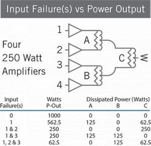
Isolating Termination Dissipation
Isolating terminations enable the dissipation of power due to various unbalances and possible input failures. In the case of high power RF Combiners - RF Dividers from Werlatone, however, it may be a system layout and/or cost which determine whether to include internal terminations with enough dissipation capability to absorb the unbalanced power that results from one or more input failures.
A schematic representation of four 250 Watt amplifiers feeding a 4-Way RF Combiner, outlines the power output and the power dissipation requirement associated with various input failure scenarios. It should be noted that all losses shown in the chart are independent of the combiner insertion loss.
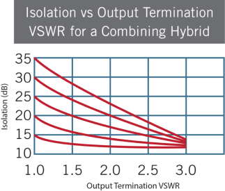
Isolation vs Output Termination VSWR For a Combining Hybrid
Inherent isolation degrades as a function of Output Termination VSWR. As the Output Termination VSWR approaches 2.5:1, a combiner with infinite Inherent Isolation, provides only 2 dB more Isolation than one with 15 dB Inherent Isolation, and only 1 dB more than a unit with 20 dB Inherent Isolation. Therefore, any investment in a unit with greater than 20 dB Inherent Isolation, operating into an Output Termination VSWR greater or equal to 2.5:1, should be reviewed.
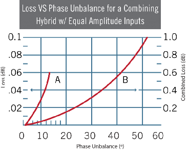
Loss vs Phase Unbalance
The difference in phase delay from any input to the sum port. Most units exhibit a typical Phase Unbalance of 1-5 degrees.
Curve A illustrates how Phase Unbalance influences the loss of a 2-Way Combiner. Since even a 10 degree Phase Unbalance results in only 0.033 dB loss above insertion loss, in certain applications the Phase Unbalance may be over specified.
Curve B may be utilized to determine the Combined Loss due to the Phase Unbalance of a combiner and two driving amplifiers. As an example, two amplifiers phase tracked to 15 degrees and a combiner with 10 degrees Phase Unbalance, results in a loss of approximately 0.22 dB above the insertion loss. The power represented by the 0.22 dB loss is dissipated within the isolation termination(s).
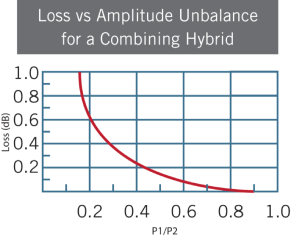
Loss vs Amplitude Unbalance
Any unbalance in amplitude between the input ports to a combiner (expressed as P1/P2), while driving from two identical RF sources.
Amplitude Unbalance affects the loss of a Combiner / System. On a 2-Way Combiner, extending the P1 / P2 axis to < 0.1, shows that a complete failure of one input source results in a loss of 3 dB. Thus, one-half of the input power reaches the output, while one-half dissipates within the isolation termination(s). As an example, one RF source (P1) generating 100 Watts and the other RF source (P2) generating 200 Watts will provide an unbalance ratio (P1 / P2) of 0.5. The resulting loss due to this Amplitude Unbalance is approximately 0.13 dB.